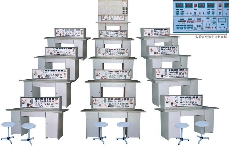
KRA-2000G Electricians, analog circuits, digital circuits, electrical control (with DC motor experiment) laboratory equipment [5-in-1)
At present, the domestic types of schools electrician, electronics, simulation, digital electronic circuits, electrical equipment mostly experimental control of the points, some schools in teaching demands made in various forms of experimental test-bed or box, because less processing by its processing capacity constraints, processing crude, dysfunction, failed to meet the test requirements, equipment and personal accident-prone, and difficult to purchase many experimental components, difficult to manage, it is difficult to test out the outline provisions experiment. For these, domestic companies from Germany and the merits of similar products in light of China's higher education, vocational education CAI Xue outline requirements of the development of this product
Product characteristics:
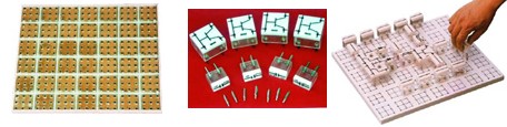
Experimental Taiwan has better security protection measures, more complete function. Test-bed tables with a common central circuit board, board injection from the surface there are cloth abalone into a group of mutual Unicom jack, component box on arbitrary in its fight inserted into experimental circuits, without a box box transparent, intuitive good, the lid will never fade printed with the device symbols, lines clear aesthetic. Box with lid to use more scientific pressure style structure, maintenance removable convenience. Experimental components placed in a drawer about The above table, greatly improving the management level, thereby reducing the teacher-testing work.
Scope of application:
Equipment apply to colleges, universities, secondary, vocational school and technical school, and so the electrician, electrical principles, simulated electronic technology and digital circuits, electrical control equipment, and other courses experiment. The device is the upgrading of the existing laboratory equipment or newly built, expanded, the ideal laboratory products. It is equipped with the level of school, grade A an important indicator.
Structure and Properties:
1, power and parameters:
(1) Input voltage: four-three-phase power supply, input indicator light.
(2) Power output: a fuse and leakage protection shape secondary protection.
Group A: single, three-phase AC power adjustable, providing three-phase 0 ~ 430 V AC power supply for adjustable, can be 0 to 250 V single-phase adjustable power supply (equipped with a 1.5 KVA three-phase autotransformer regulator ), equipped with three tables Pointer AC voltage, the output voltage regulator instructions.
Group B: low-voltage AC voltage 3 ~ 24 V adjustable seven stalls, the maximum output current of 1.5 A, ammeter instructions.
Group C: low voltage DC power supply, voltage 5 V, current 0.5 A, ammeter instructions.
Group D: dual steady flow regulator power supply, 2P output voltages are 0 to 30 V, the multi-turn potentiometer for adjusting output maximum current of 1.5 A, each power output is 0.5 ammeter, the voltage meter instructions. Voltage stability of <10 ˉ, load of <10 ˉ, ripple voltage <5 mV.
Group E: single-phase AC electricity output, user-owned equipment for use.
2, function signal generator:
(1) waveforms: sine, triangle wave, square wave, pulse wave, sawtooth, square wave TTL.
(2) frequency range: from 0.1 Hz to 2 MHz, the frequency at seven stalls at.
(3) sine wave distortion :10-30 Hz <3% 30Hz - 100KHz ≤ 1%.
(4) square wave response: forward / backward along ≤ 100 nS (open circuit)
(5) The maximum output range (open): f <1MHz range ≤ 20 Vp-p
1 M <f ≤ 2 MHz rate ≤ 16 Vp-p
(6) DC bias (open): ± 10V
(7) output impedance Z: ZO == 50 ohms ± 5 Ω
(8) duty cycle: pulse and ramp up, falling edge can be continuous changes in the scope of 10% -90%.
(9) Voltage Controlled Oscillation (VCF): plus DC voltage of 0 ~ ± 5V change, corresponding changes in the frequency of greater than 100:1.
(10) output attenuation: 20 dB 40dB 60dB.
3, frequency counters:
(1) measuring frequency range: 1 Hz ~ 100MHz.
(2) gate Time: 0.01 S, 0.1S, 1S, 10S.
(3) input impedance (AC coupling): resistance weight of about 500 K Ω, parallel capacitance of about 100 P.
4, single pulse: one pair of each output can be positive and negative pulses.
5, audio power amplifier: audio input voltage of not less than 10 mV output power of not less than 1 W, adjustable volume, with speakers for amplification circuit PA, but also can be used for signal tracing.
6, paragraph 107 decoder (KRA - 2000A Electrotechnical Laboratory complete sets of equipment there is no such function): 3 Group paragraph 107 decoder and the corresponding display digital decoding.
7, AC-DC, measured by the ammeter: Precision 0.5, the three semi-digital display, measuring range: 0 to 1000 mA.
8, which has been used by AC-DC voltage Table 2: Precision 0.5, the three semi-digital display, measuring range: 0 to 99.9 V.
9, experimental operating tables: decorative panels made of double-sided, deformation not fade, size: 1600 × 700 × 800cm, modeling aesthetic generous, with the middle drawer, storage tool, about two storage cabinets, storage components for .
Equipment with: (24 for example)
1, students experiment tables:
Experimental operating table 12 (table 2), the central operating table tablecloths set up common circuit Flashboard (size: 350 × 900mm), according to the experimental circuits on arbitrary in its fight boxes inserted into experimental circuit components. Components box transparent intuitive box, the contents components can be clearly seen lid and India have never faded components symbols, lines clear aesthetic, with the lid of the box using pressure-style structure, maintenance removable replacement convenience. Each operating tables equipped with a rubber plate, the protection circuit Flashboard generic desktop. Experimental lower operating tables have two components storage cabinets, placed experimental components and storage plate.
2, showing the console:
The tables show the experimental operation, the test-bed, presentation control screen composition, respectively control 12 students test-bed power. Li Ping demonstrated in experimental stage, size: 1600 × 700mm, for the demonstration on.
3, equipment equipped with:
39 Pointer 1.5 DC ammeter, 26 units three-phase 180 W motor, 13 200W DC motor, 26 hours relays, 78 exchanges and contacts, 13 MF500 - Multimeter, 13 Digital Multimeter, 39 beacons 52 trip switch, 78 control buttons, 13 inverted-switch, 26 transformers, 13 three-phase two-vote switch, 13 three-phase switching, 13 sets of experiments necessary resistance, potentiometer, inductance, capacitance, SCR, FET, three tubes, rectangular magnets, integrated circuits, logic level switching, 25 sets of electric iron and melt-size metal frame that came, 13 sets of stripping wire pliers and top pliers, screwdrivers and other tools, 91 integrated Block , 39 current test socket module boxes, and other components (components have been installed in the unit placed inside the box), 25 stool.
4, user-owned equipment: dual-trace oscilloscope (model limited), power meter, Millivoltmeter, slippery lines rheostat.
Pilot projects:
Electrician:
Electrician:
1, the use of Electrical Measurement Instrument
2, used the identification and detection devices
3, linear and nonlinear components of components voltammetry
4, the characteristics of the power supply
5, the potential value of the voltage value of
6, ammeter, and the expansion-Voltage Meter
7, Kirchhoff's law certification
8, the certification Lenz's Law
9, the principle of superposition and certification reciprocity theorem
10, Norton theorem Thevenin's theorem and the test
11, voltage and current source of the equivalent transformation
12, controlled source of research
13, a band circuit experiment
14, the Second Circuit transition process
15, Research LC components in the DC Circuit and the exchange of
16, the maximum power load conditions 17, the measurement circuit parameters exchange
18, sine exchange components of RLC circuit
19, RL and RC series circuit experiment
20, RLC series resonant circuit
21, fluorescent circuit connections and power factor improvement
22, the three-phase load Star, 1.30 Next Act
23, the three-phase circuit and power measurement
24, RC network of selected frequency
25, two-port network study
26, single-phase transformer experiment
27, mutual inductance circuit experiment
28, the use of three-phase asynchronous motors with starter
29, 3-phase motor control relay contact with the basic circuit
30, Y-3-phase motor starting control experiment △
31, the order of three-phase motor control experiment
32, 3-phase motor control braking energy experiment
Use of these 32 experiments can be completed the following components circuit experiment
33, the simplest circuit
34, Circuit points potential and the choice of reference point
35, the series resistance
36, the parallel resistance
37, Resistance Hybrid
38, resistor divider circuits
39, the entire circuit Ohm's law
40, Bridge Application and balance conditions
41, node voltage Law
42, loop voltage Law
43, slip Current law
44, RCL parallel circuit
45, Series circuit
46, transformers structure and working principle
47, the first law Kirchhoff
48, Kirchhoff Second Law
49, fluorescent circuit principle
50, expanding voltage meter range
51, expanding range ammeter
52, RC circuit transition process
53, RL transition process
54, the series circuit capacitance
55, the parallel circuit capacitance
56, the charge and discharge capacitors
57, AC-DC capacitor in the role of
58, bar magnet coils in the campaign
59, capacitor Hybrid
60, pure resistance, inductance, capacitance circuit
61, the magnetic coupling coil-Series
62, the opposite of magnetic coupling coil in series
63, the working principle of Ohm Table
64, double-switch in the control of different voltage resistance
65, with oscilloscope observed hysteresis loop
66, magnetic circuit Ohm's law
67, the two coils of the same name - and mutual inductance
68, mutual inductance coupling
69, improve power factor method
70, single-phase power measurement circuit
71, and hand power circuit
72, filter circuit
73, the relationship between resistance and temperature: measured filament voltammetry
74, three-phase induction motor control switch is to experiment
75, the control circuit with overload protection
76, the button control is to reverse control circuits
77, contactor control of a triangular buck Star starter control circuit
Analog circuit experiment:
1, the diode is, the inverse of
2, Crystal triode input, output characteristics
3, a total of emitter transistor single-tube amplifier
4, capacity levels coupled amplifier
5, negative feedback on the performance of amplifier
6, FET amplifier
7, differential amplifier circuit
8, operational amplifier testing indicators
9, the basic Integrated Operational Amplifier Applications
10, Integrated Operational Amplifier nonlinear applications (multiple Waveform Generator)
11, transformer coupled push-pull power amplifier
12, OTL power amplifier
13, Integrated Power Amplifier
14, single-phase bridge rectifier circuit
15, Series transistors DC Power Supply (design of experiments)
16, Integrated DC Power Supply
17, single-junction transistor characteristics
18, single-junction transistor trigger circuit
19, thyristor simple test (multiple computing circuit simulation)
20, thyristor controlled rectifier circuit
Use of these 20 experiments can be completed the following components circuit experiment
1, the negative feedback voltage bias circuit
2, pressure Current negative bias circuit
3, using diode stability point
4, common base amplifier
5, a total collector amplifier
6, a total of the basic amplifier circuit source
7, the total market will drain circuit
8, a total gate field effect transistor circuit
9, single-tube circuit resistive and capacitive Large
10, transformer coupled amplifier
11, A Power Amplifier
12, Series circuit current negative feedback
13, series of negative feedback circuit voltage
14, parallel negative feedback circuit voltage
15, parallel negative feedback circuit current
16, a total of a total emitter amplifier
17, the bootstrap circuit emitter output
18, NPN PNP direct-coupled amplifier
19, with the elimination of negative feedback self-excited oscillation
20, transistors switch role
21, transformers feedback oscillation circuit
22, capacitance three-point oscillation circuit
23, inductance three-point oscillation circuit
24, the differential amplifier circuit, the basic form of
25, Elliot differential amplifier circuit
26, Double Power Elliot differential amplifier circuit
27, Wan Fang exchange ratio for Large
28, RP-import protection measures
29, with the input of the protection measures
30, the power supply to the protection of the wrong polarity
31, RC circuit Qualcomm
32, used to protect devices triode
33, differential input circuit operation
34, Rapid integral circuit 35, the first order differential equations circuit simulation
36, second-order differential equations circuit simulation
37, on several basic computing circuits
38, practical differential electronic circuit
39, opposes few basic amplification circuit
40, a simple comparison circuit zero
41, use as a diode circuit limit detection rate of choice
42, the minimum rate of choice circuit
43, RC passive networks low-pass filter circuit
44, with the input of the first order low-pass filter circuit
45, RP-importation of the first order low-pass filter circuit
46, a simple second-order RC filter circuit
47, the typical second-order low-pass RC filter circuit Active
48, the typical second-order Qualcomm active filter circuit
49, the basic band-pass filter circuit
50, a typical band-pass filter circuit
51, filling wave oscillation circuit
52, adjustable width of the rectangle wave generator
53, amplitude and frequency adjustable sawtooth generator
54, single-phase half-wave rectifier circuit
55, single-phase full-wave rectifier circuit
56, capacitor filter circuit
57, capacitor filter with resistance load
58, RC filter circuit
59, basic LC filter circuit
60, twice the pressure rectifier circuit
61, three times the pressure rectifier circuit
62, basic regulator circuit
63, the basic adjustment of the voltage regulator circuit
64, a larger part of the regulator circuit
65, single-phase half-wave rectifier SCR
66, electronic voltage regulation circuit
67, e-hypnosis - one interesting experiment
68, electronic doorbell circuit - interesting experimental bis
69, the electronic alarm circuit - interesting experiment ter
Digital Electronic Circuit Experiment:68, electronic doorbell circuit - interesting experimental bis
69, the electronic alarm circuit - interesting experiment ter
1, TTL integrated testing the parameters of logic gate
2, the parameters of CMOS logic gates test
3, TTL integrated electrode open doors and door three-state output Application
4, and non - or, experiment with non-gate circuit
5, using gate circuit encoder, distributor, selector
6, the combination of circuit design ------ transcoding
7, the combination of circuit design bis ------ Display Circuit
8, synchronous sequential circuit design
9, computer timing circuit design
10, the testing and application integration timer
11, JK D-type flip-flop into Trigger
12, D-type flip-flop into JK flip-flop
13, CMOS integrated A / D, D / A converter circuit experiment
14, MSI shift register and its application
15, decoder and transform way
16, MSI data selector and logic design
17, differential single steady-state circuit
18, ring more harmonic oscillator
19, a half adder circuit experiment
20, full adder circuit experiment
21, RS flip-flop experiment
22, D flip-flop experiment
23, JK flip-flop experiment
24, T Trigger experiment
25, counters experiment
26, diode-door, or gate circuit
27, triode-door, and non-door, or gate circuit
28, asynchronous counter metric subtraction
29, asynchronous counter metric Adder
30, comprehensive training experiment - electronic stopwatch
Electrical control experiments:
1, is to switch control circuit
2, contactor is to move the control circuit
3, a self-locking is to control the line
4, with overload protection is to control the line
5, inverted-switch control is to reverse control circuits
6, contact the interlock device is to reverse control circuits
7, the button is to reverse the interlock control circuit
8, buttons contactor control circuit composite Interlocking
9, automatic control circuit from the itinerary
10, contactor control series resistance buck Starting Line
11, time relay control of blood pressure control line series resistance
12, manually Y / △ buck Starter
13, contactor control Y / △ buck Starter
14, time relay control Y / △ buck Starter
15, QX-13-Y / △ automatic starter control circuit
16, half-wave rectifier power brake control circuit
17, full-wave rectifier power brake control circuit
18, C620 lathe electrical control circuits
19, manually buck Starter
20, single-phase operation of brake control circuit reverse
21, electric hoist electrical control circuits
22, C6163 lathe electrical control circuits
23, control circuit interlock control circuit
24, the main circuit interlock control circuit
25, the DC motor launch
26, the DC motor speed control
27, the DC motor reversal
28, DC mechanism dynamic experiment
Experimental use of the above components, but also the completion of dozens of experiments, in this not individually enumeration.
电工、模电、数电、电气控制(带直流电机实验)实验室设备〔五合一)1, is to switch control circuit
2, contactor is to move the control circuit
3, a self-locking is to control the line
4, with overload protection is to control the line
5, inverted-switch control is to reverse control circuits
6, contact the interlock device is to reverse control circuits
7, the button is to reverse the interlock control circuit
8, buttons contactor control circuit composite Interlocking
9, automatic control circuit from the itinerary
10, contactor control series resistance buck Starting Line
11, time relay control of blood pressure control line series resistance
12, manually Y / △ buck Starter
13, contactor control Y / △ buck Starter
14, time relay control Y / △ buck Starter
15, QX-13-Y / △ automatic starter control circuit
16, half-wave rectifier power brake control circuit
17, full-wave rectifier power brake control circuit
18, C620 lathe electrical control circuits
19, manually buck Starter
20, single-phase operation of brake control circuit reverse
21, electric hoist electrical control circuits
22, C6163 lathe electrical control circuits
23, control circuit interlock control circuit
24, the main circuit interlock control circuit
25, the DC motor launch
26, the DC motor speed control
27, the DC motor reversal
28, DC mechanism dynamic experiment
Experimental use of the above components, but also the completion of dozens of experiments, in this not individually enumeration.
SHANGHAI KERONG TEACHING APPARATUS CO.,LTD
 English Tel: +86.21-56301098 Fax: +86.21-66613899
QQ: MSN:
MSN: shkr123@hotmail.com
Website: www.shkr.com Email: kerong@shkr.com
English Tel: +86.21-56301098 Fax: +86.21-66613899QQ:
MSN:shkr123@hotmail.comWebsite: www.shkr.com Email: kerong@shkr.com